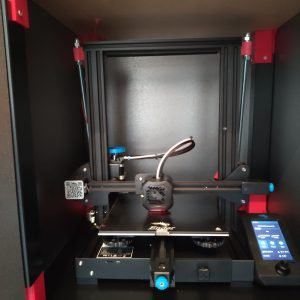
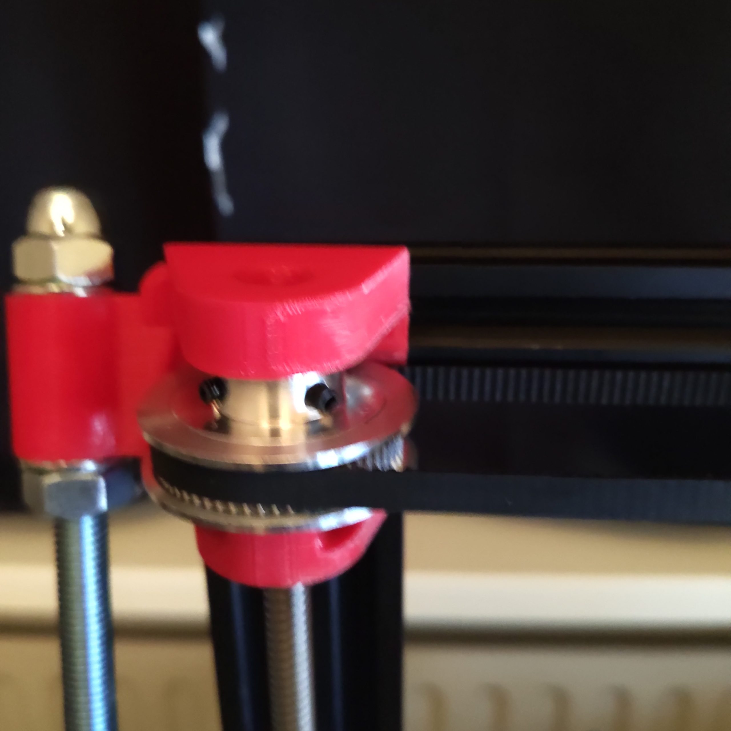
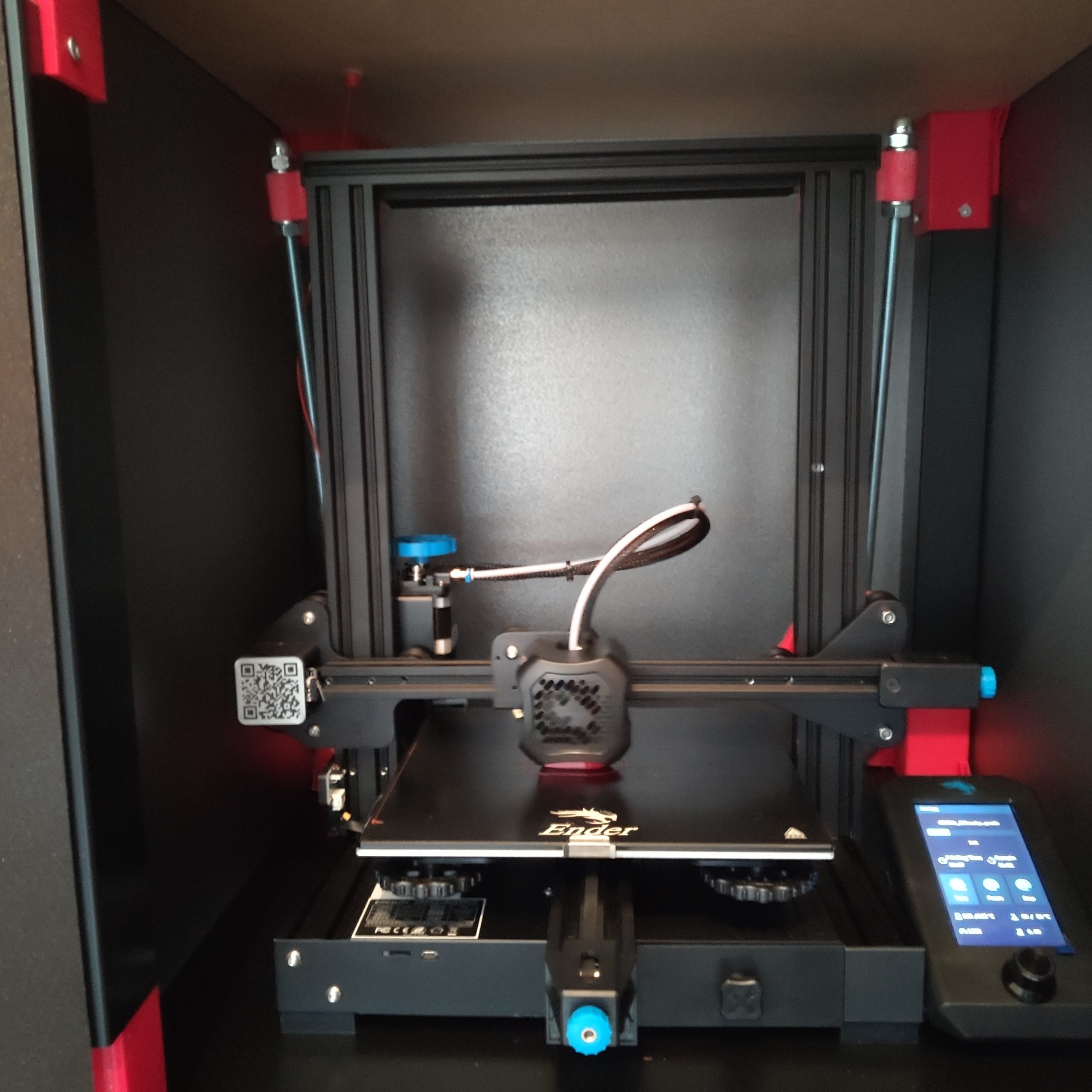
I just started with 3d printing and did some research how reliable the printer whas and found out the there where a few mods available on the internet. At some point a video in my recommendation showed up after 1000 youtube video’s and how to’s it whas called Ender 3 pro build: Starting off properly from the channel Proper Printing.
So after watching his video a saw that he uploaded a new video called Ender 3 pro dual Z axis. i checked my printer and it had the same problem on the front left side the there whas some slack so this is my journey how i putted it together.
Please subscribe to Proper Printing he deserves it.
Shopping list (links from: reprapworld.com):
- 2x GT2 pulley (60 teeth / 6 mm belt/ 42mm outer diameter/8mm bore)
- 1x GT2x6mm Timing belt (696mm closed)
- 1x TR8X8 – Leadscrew nut 8mm
- 1x TR8X8 Lead screw (8 mm / 8 mm per rev. / 30 cm)
- 4x 608ZZ Shielded ball bearing
– M3 – - 4x M3x10 hexagon bolt
- 4x M3x5.2mm inserts could not found on reprapworld so bought them on ebay
– M5 – - 14x M5×10 hexagon bolt
- 14x M5 washer
- 14× Slide nut M5 for 20×20 extrusions
– M10 – - 2× M10 threaded rod 480mm length. Yes, you can get two out of a 1m rod :D. I recommend mounting the braces first and to measure it yourself in case you have a different outcome. link: 1meter rod
6× M10 hexagon nut
2× M10 hexagon domed cap nut yes, you can use regular nuts, but these look way better
8× M10 washer
After happy shopping and the time that you need to wait you can print the parts in the meanwhile 😀 win win.
Things that you need to print :
Go to the website : https://properprinting.pro/product/ender-3-dual-z-axis-with-optional-frame-braces/ and download the file
“You can enter any value in the price field to make a donation. Don’t want to donate? Simply enter an amount of 0″
Give him some money .
After you have downloaded the zip file that you receive in your mail extract it and it should look like this :
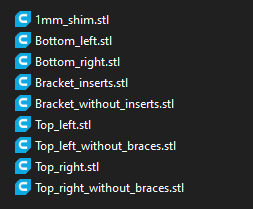
Now there a few version’s in this zip without insters and braces
So the version without we don’t need to print.
Print settings:
Printer: Ender 3 Pro V2
Rafts: No
Supports: Yes
Resolution: 0.2
Infill: 20%
Filament: PETG
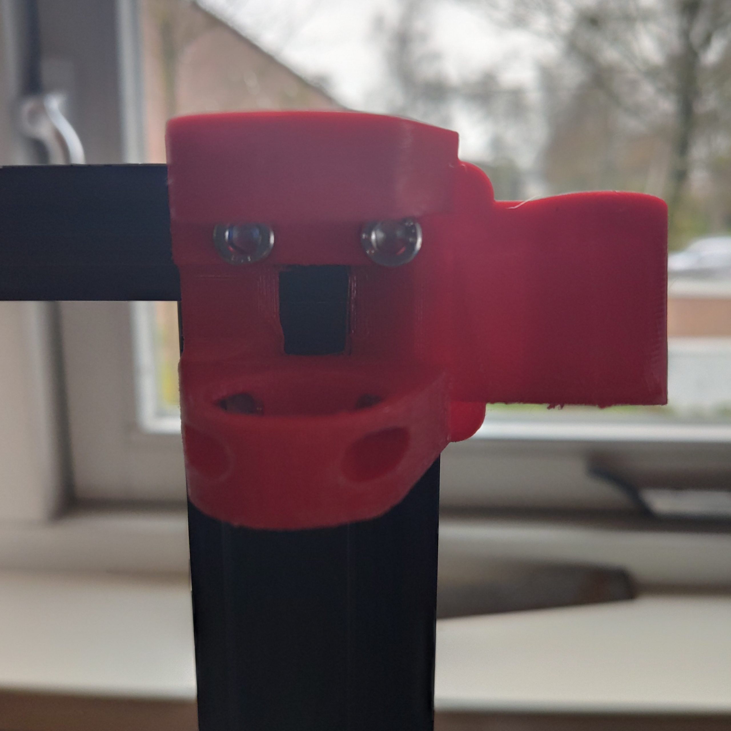
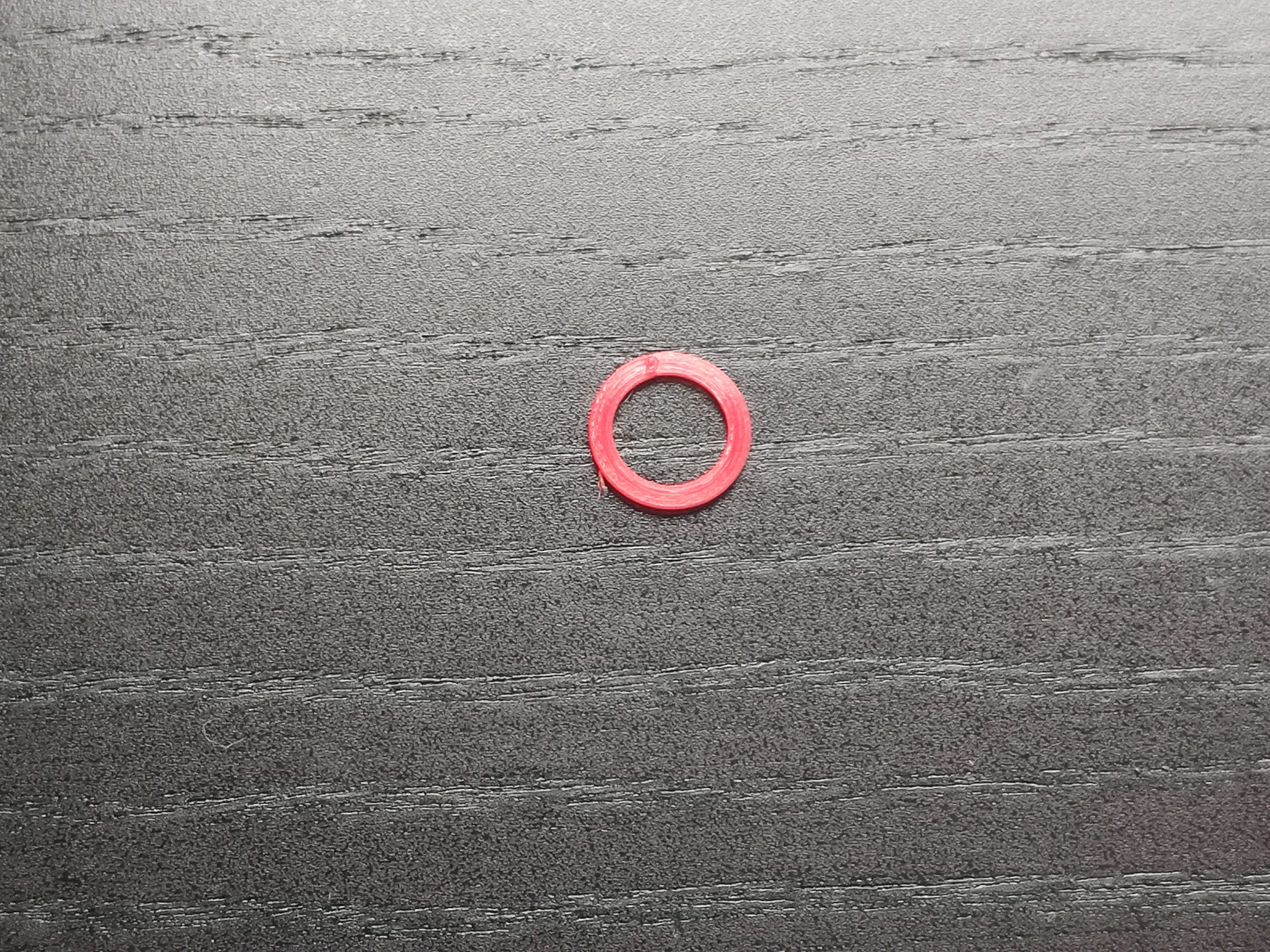
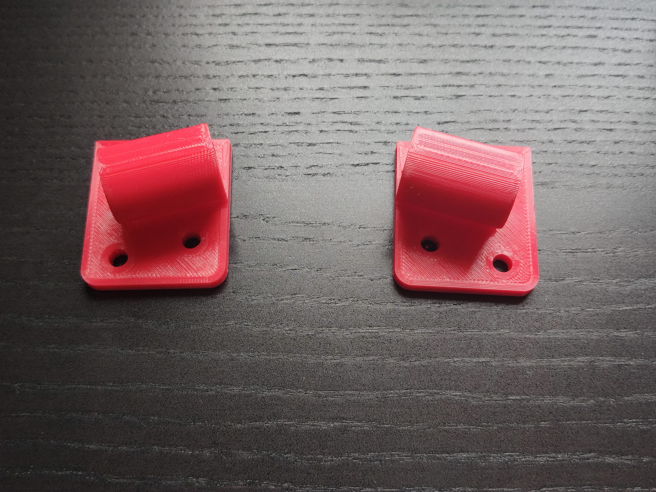
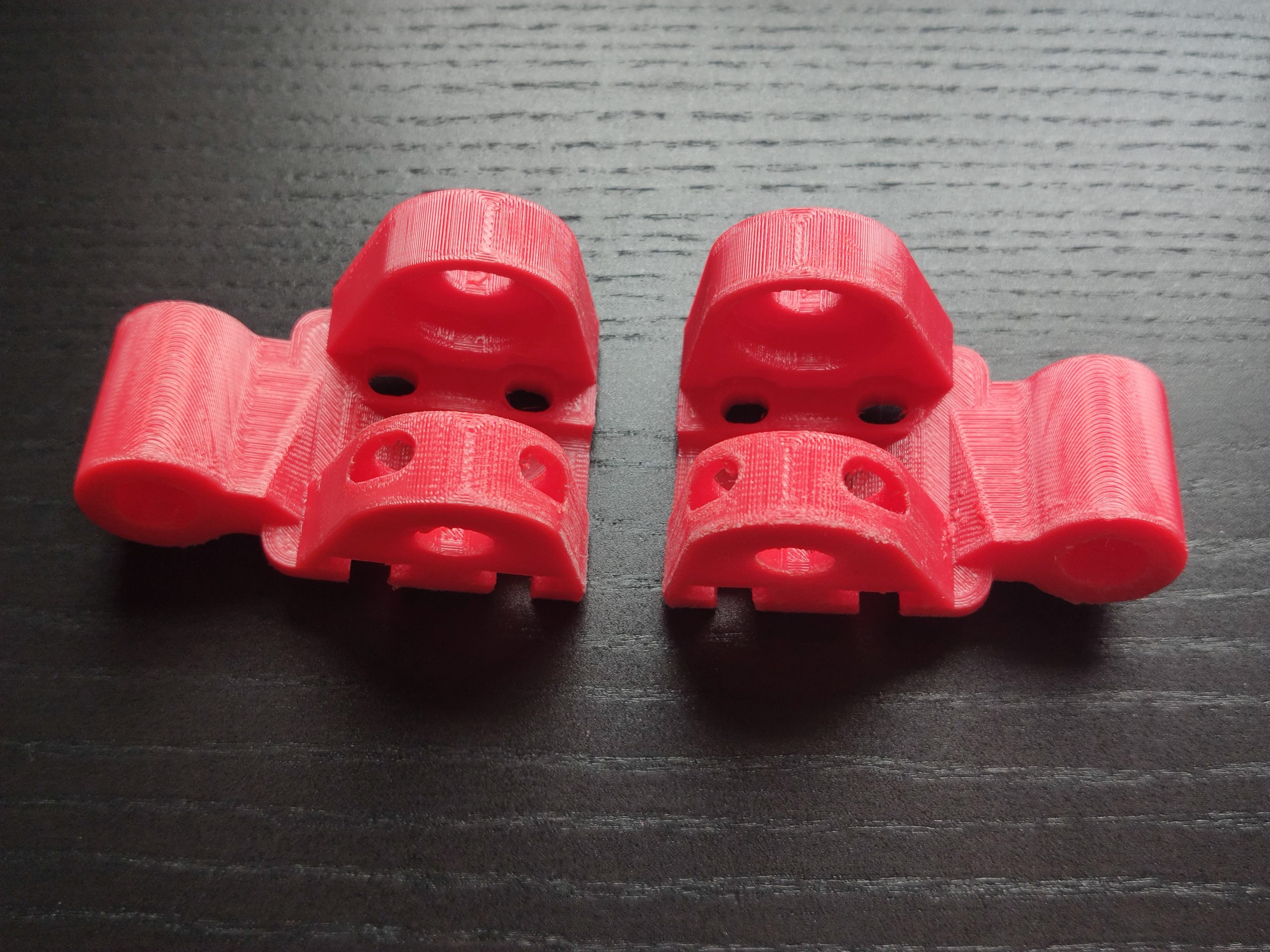
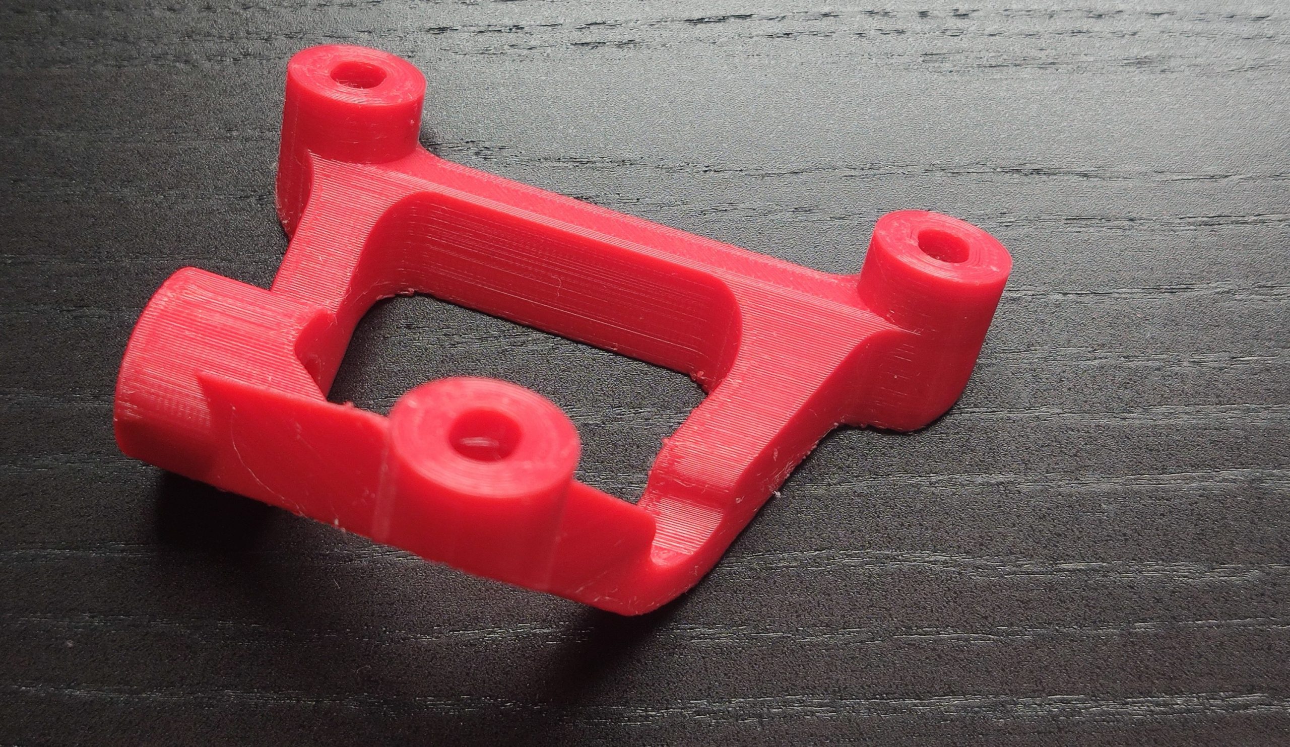
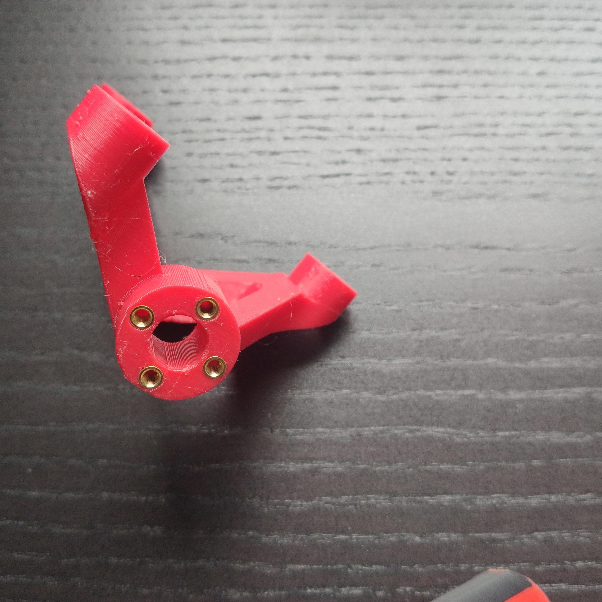
After printing your pieces should look like this :
1mm shimm
Bottom left & right
Top left & right
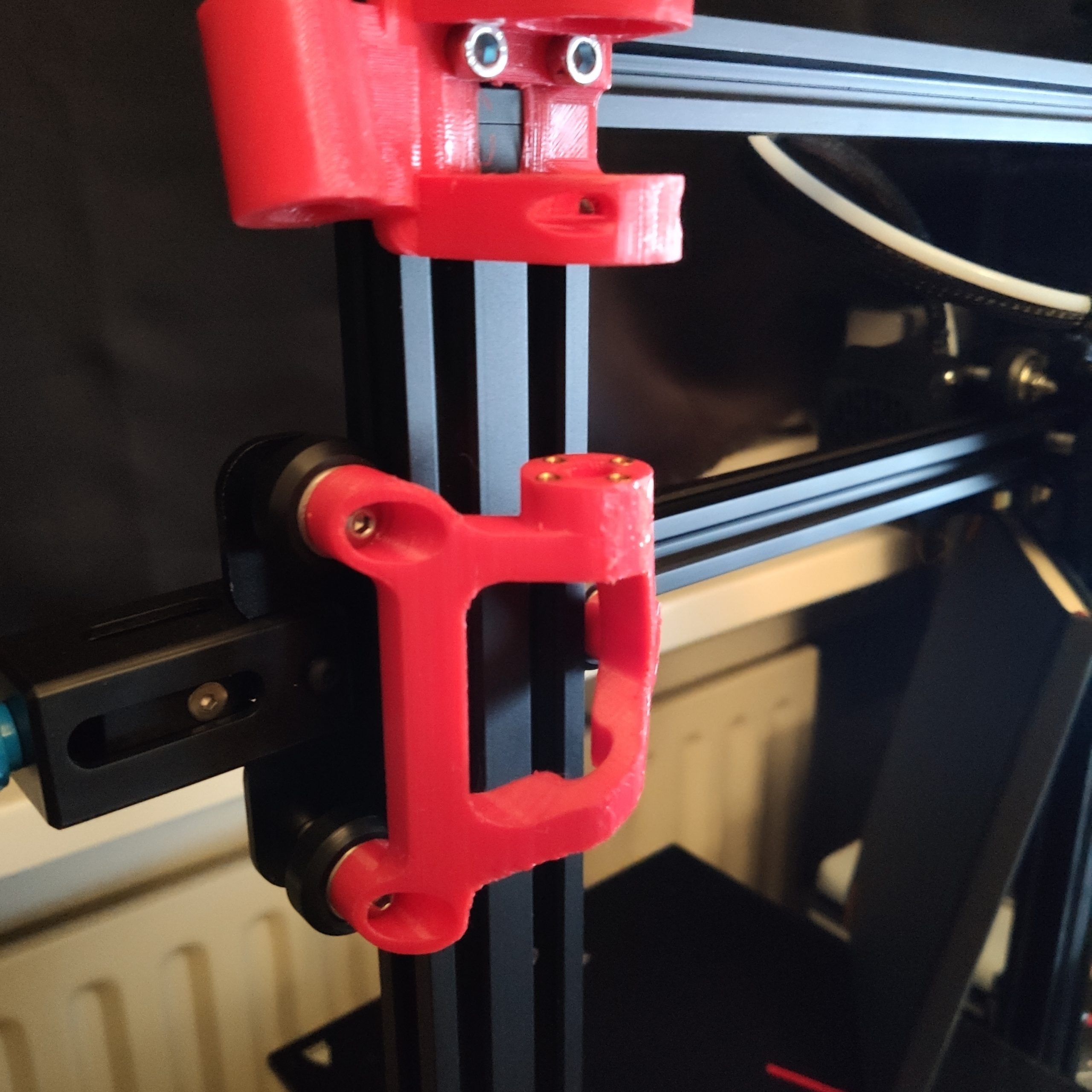
Bracket with inserts
Let’s get started:
- Remove the power supply and Z-axis motor leave the existing lead screw in (i have removed the Z-axis motor to make the frame straight you will see why in the next steps)
- Remove both top end caps (in my case it whas not needed)
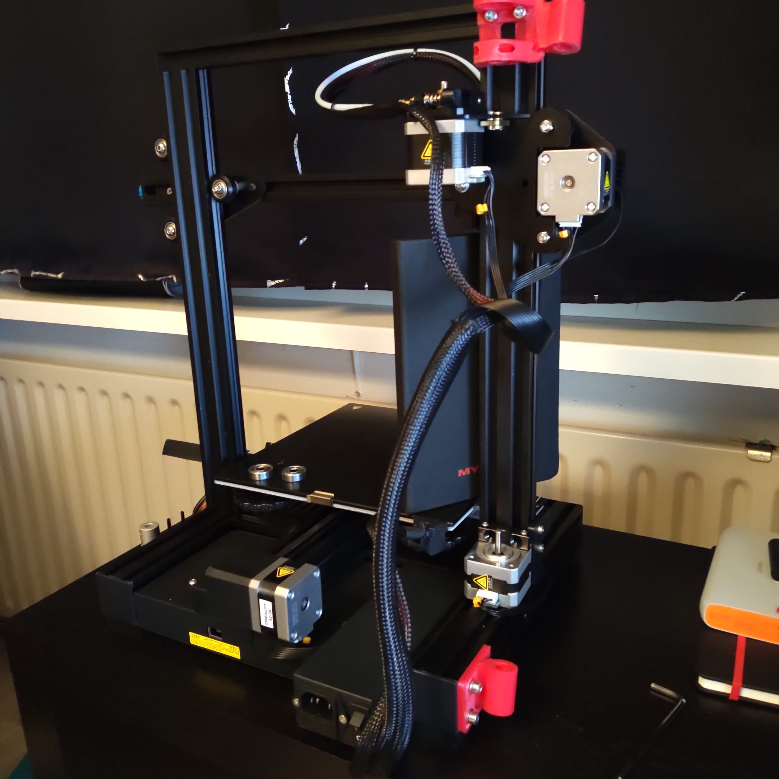
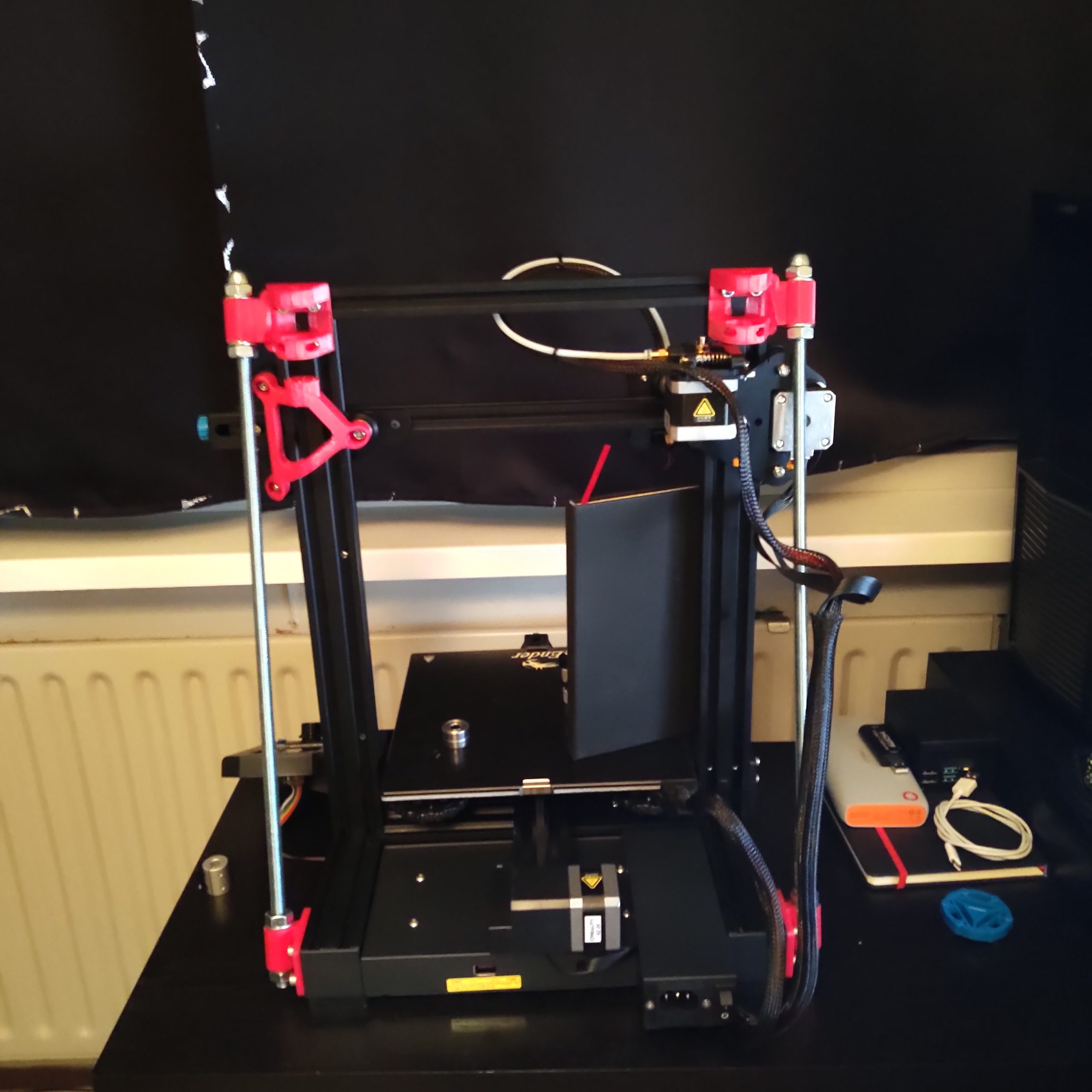
- Place the top right corner piece (the one above the Z-motor) do not tighten it down
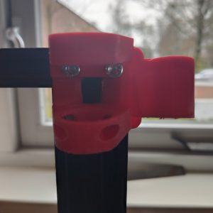
- Place the bottom right corner piece next to the Z-motor do not tighten it down
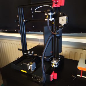
- Now insert the m10 rod and make sure it’s aligned then tighendown the nuts from step 3 & 5.
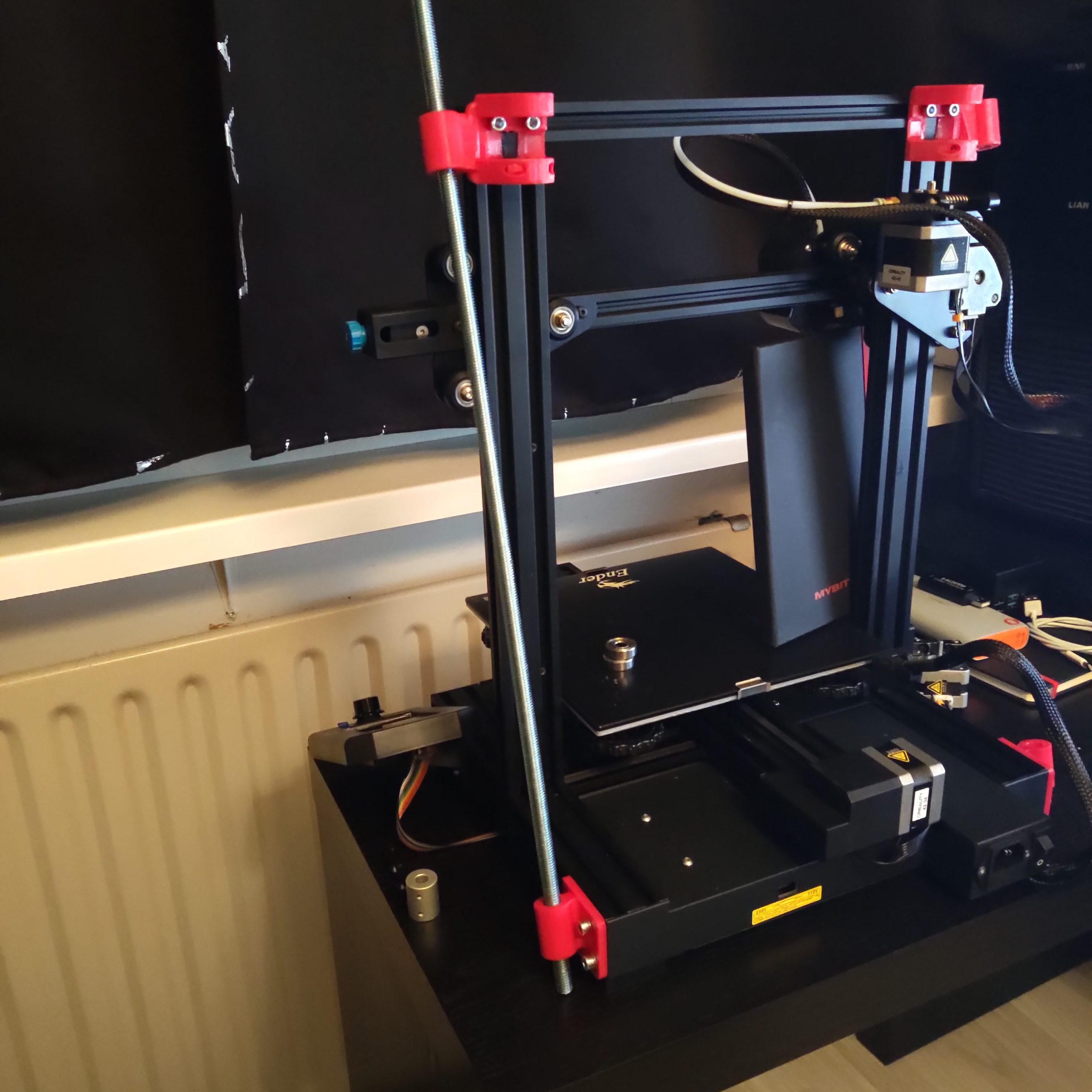
- Add the top left corner piece do not tighten it down
- Place the bottom left corner piece do not tighten it down
- Now insert the m10 rod and make sure it’s aligned then tighendown the nuts from step 8 & 9.
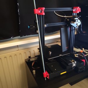
- Add now the bracket
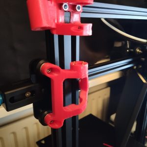
- Now make sure your printer is perpendicular here is why i removed the z-axis to get a good measurement : https://youtu.be/nBVrcIZ095Y
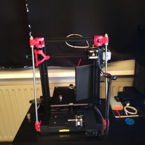
- Now back to the right side where the Z-Axis is. put the Z-axix back in place and continue with
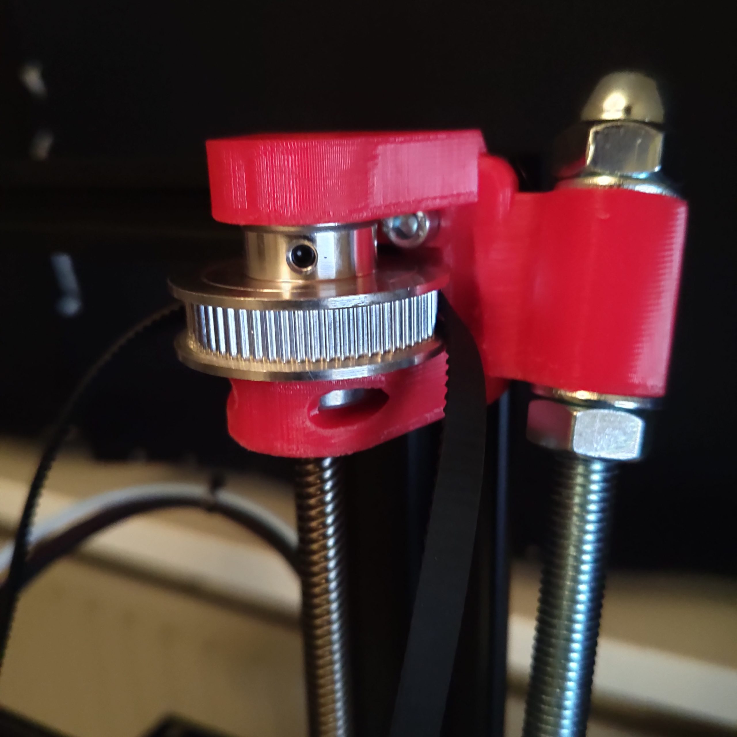
- Press both bearings in in the top right
- Press the existing lead screw through the lower bearing and add the pulley together with the timing belt
- Press the lead screw through the pulley, the upper bearing and far enough for the Z-motor and coupler
- Place the Z-motor and mount it to the lead screw
- Fasten the pulley
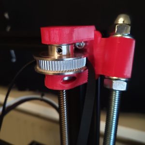
- Now move to the left side
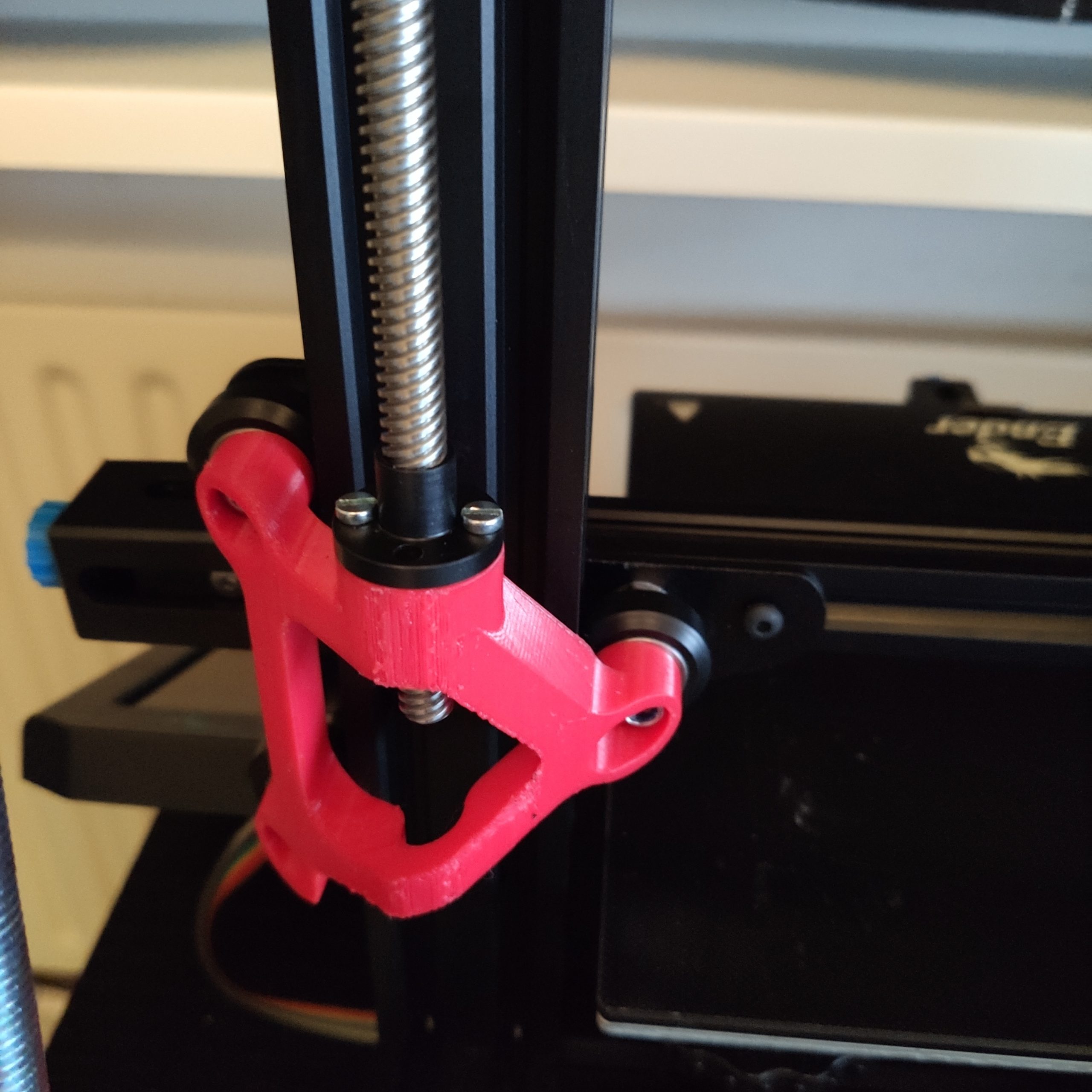
- Add the bracket with the 300mm lead screw and nut (use a 10mm drill to widen the hole for the lead screw nut if necessary) and do not press the lead screw nut in yet
- Press the 300mm lead screw through the lower bearing and add the second pulley together
- Press the 300mm lead screw to the right height (just above the upper bearing) don’t fasten the pulley yet
- Press the lead screw nut in the bracket by rotating it downwards and mount it
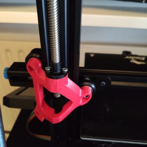
- Adjust the height of the gantry so that both sides are at the same height. This can be done by rotating the 300mm lead screw and holding the pulley still
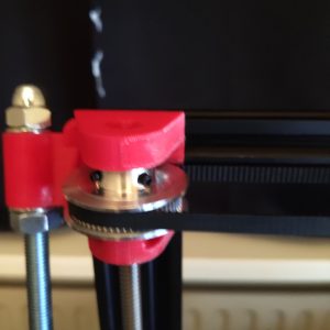
- Once the gantry is horizontal you can fasten the second pulley and enjoy printing